SUBMERGED ARC WELDING
A flat arc process - (constant) voltage. It is used in beam, boom, tractor and multi-head type rigs.
Type of Operation.
Mechanised, automatic or semi-automatic.
Mode of Operation.
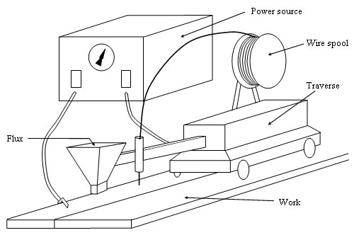
An arc is maintained between the end of a bare wire electrode and the work. As the electrode is melted, it is fed into the arc by a set of rolls, driven by a governed motor. Wire feed speed is automatically controlled to equal the rate at which the electrode is melted, thus arc length is constant (similar to MIG/MAG - constant voltage). The arc operates under a layer of granular flux, hence submerged arc. Some of the flux melts to provide a protective blanket over the weld pool. The remainder of the flux is unaffected and can be recovered and re-used, provided it is dry and not contaminated.
A semi-automatic version is available in which the operator has control of a welding gun that carries a small quantity of flux in a hopper.
Process And Equipment Fundamentals.
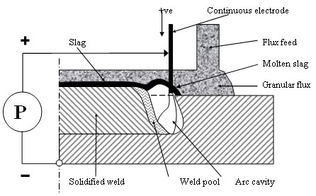
The principles of the submerged arc process are shown schematically below. A power source P, is connected across the contact nozzle on the welding head and the work piece. The power source can be a transformer for AC welding, or a rectifier (or motor generator) for DC welding. The filler materials are an uncoated continuous electrode and a granular welding flux fed down to the joint by way of a hose from the flux hopper. To prevent the electrode overheating at high currents the welding current is transferred at a point very close to the electric arc. The arc is burning in a cavity filled with gas (CO2, CO, etc.) and metal fumes. In front, the cavity is walled in by unfused parent material, and behind the arc by solidifying weld metal. The covering over the cavity consists of molten slag. The diagram below also shows the solidified weld and the thin covering of solid slag, which has to be detached after the completion of each run.
Since the arc is completely submerged by the flux there is no irritating arc radiation that is characteristic of the open arc process - welding screens are therefore unnecessary.
The welding flux is never completely consumed so the surplus quantity left can be collected, either by hand or automatically, and returned to the flux hopper to be used again.
Although semi-automatic submerged arc welding equipment exists and is convenient for certain applications, most submerged arc welding uses fully mechanised welding equipment. One of the main virtues of the submerged arc process is the ease with which it can be incorporated into fully mechanised welding systems to give high deposition rates and consistent weld quality. Weld metal recovery approaches 100% since losses through spatter are extremely small. Heat losses from the arc are also quite low due to the insulating effect of the flux bed and therefore the thermal efficiency of the process can be as high as 60%, compared with about 25% for MMA welding.
Flux consumption is approximately equal to the wire consumption, the actual ratio - weight of wire consumed: weight of flux consumed - being dependent on the flux type and the welding parameters used.
Welding parameters are maintained at their set values by the arc control unit. A feed back system is usually used to maintain a stable arc length so that a change in arc length (corresponding to a change in arc voltage) will produce an increase or decrease in the wire feed speed until the original arc length is regained.
Joint Preparation.
Joint preparation depends on plate thickness, type of joint e.g. circumferential or longitudinal and to some extent on the standards to which the structure is being made.
Plates of up to 14mm thick can be butt welded without preparation with a gap not exceeding 1mm or 10% of the plate thickness, whichever is the greater. Thicker plates need preparation if full penetration is to be obtained. Variable fit up cannot be tolerated.
A welder using stick electrodes can adjust his technique to cope with varying joint gaps and root faces or varying dimensions. Not so an automatic welding head. If conditions are set up for a root gap of 0.5mm and this increases to 2 or 3mm, burnthrough will occur unless an efficient backing strip is used. In such circumstances a hand welded root run using MIG or MMA is advisable. All plate edges must be completely clean and free from rust, oil, millscale, paint, etc. If impurities are present and are melted into the weld, porosity and cracking can easily occur.
Time spent in minimising such defects by careful joint preparation and thorough inspection prior to welding is time well spent since cutting out weld defects and rewelding is expensive and time consuming.
Welding procedure.
In general the more severe the low temperature notch toughness requirements, the lower the maximum welding current that can be used. This is to minimise heat input and means that a multipass technique may be required. When welding stainless steels the heat input should be kept low because it has poor thermal conductivity and a high coefficient of expansion compared with mild steel. These two effects lead to overheating and excessive distortion if large diameter wires and high currents are used. Multi-run welds using small diameter wires are therefore recommended for stainless steels and high nickel alloys such as Inconel.
Welding Parameters.
Selection of the correct welding conditions for the plate thickness and joint preparation to be welded is very important if satisfactory joints free from defects such as cracking, porosity and undercut are to be obtained. The process variables, which have to be considered, are:
- Electrode polarity.
- Welding current.
- Electrode diameter.
- Arc voltage.
- Welding speed.
- Electrode extension.
- Electrode angle.
- Flux depth.
These are the variables that determine bead size, bead shape, depth of penetration and in some circumstances metallurgical effects such as incidence of cracking, porosity and weld metal composition.
a. Electrode polarity.
The deepest penetration is obtained with DC reverse polarity (DC electrode positive, DCEP)
which also gives the best surface appearance, bead shape and resistance to porosity.
Direct current straight polarity (DC electrode negative, DCEN) gives faster burn off (about 35%) and shallower penetration since the maximum heat is developed at the tip of the electrode instead of at the surface of the plate. For this reason DC electrode negative polarity is often used when welding steels of limited weldability and when surfacing/cladding since, in both cases, penetration into the parent material must be kept as low as possible. The flux/wire consumption ratio is less with electrode negative polarity than with electrode positive polarity, so that alloying from the flux is reduced.
With DC polarity the maximum current used is 1000 amperes due to arc blow problems. In changing from positive to negative polarity some increase in arc voltage may be necessary to obtain a comparable bead shape.
Alternating current gives a result about half way between DC electrode positive and DC electrode negative and usually gives a flatter, wider bead. It can be used on multihead systems and is particularly useful when arc blow is a problem. It is often used in tandem arc systems where a DC positive electrode is used as the leading electrode and an AC electrode as the trail.
b. Welding current.
Increasing the wire feed speed increases the welding current so that the deposition rate increases as the welding current increases. The wire feed speed is the most influential control of fusion and penetration. The current density controls the depth of penetration - the higher the current density the greater the penetration. For a given flux, arc stability will be lost below a minimum threshold current density so that if the current for a given electrode diameter is too low arc stability is lost and a rugged, irregular bead is obtained. Too high a current density also leads to instability because the electrode overheats and undercutting may also occur.
c. Electrode Diameter.
For given current, changing the electrode diameter will change the current density. Therefore a larger diameter electrode will reduce penetration and the likelihood of burnthrough, but at the same time arc striking is more difficult and arc stability is reduced.
d. Arc voltage.
Arc voltage affects dilution rather than penetration. Bead on plate welds and square edged closed butt welds have increased width and dilution as the arc voltage increases, but depth of penetration remains the same. If the joint preparation is open, for example in a butt joint with a small angled 'V' preparation, increasing the arc voltage can decrease the penetration.
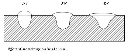
The arc voltage controls the arc length, flux consumption and weld metal properties. Increasing the arc voltage increases the arc length so that the weld bead width is increased, reinforcement is decreased, flux consumption is increased and the probability of arc blow is also increased. When alloying fluxes are used arc length, and hence arc voltage, is very important since at high arc voltages more flux is melted so that more alloying elements enter the weld metal. Thus arc voltage can affect weld metal composition.
e. Welding speed.
Welding speed or travel speed controls depth of penetration. Bead size is inversely proportional to travel speed. Faster speeds reduce penetration and bead width, increase the
likelihood of porosity and, if taken to the extreme, produce undercutting and irregular beads. At high welding speeds the arc voltage should be kept fairly low otherwise arc blow is likely to occur.
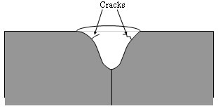
If the welding speed is too slow burn through can occur. A combination of high arc voltage and slow welding speed can produce a mushroom shaped weld bead with solidification cracks at the bead sides.
f. Electrode extension.
Also known as electrode stick out and alters the tip to work distance. Electrode extension governs the amount of resistance heating which occurs in the electrode. If the extension is short the heating effect is small and penetration is deep. Increasing the extension increases the temperature of the electrode, which decreases the penetration, but deposition rates are increased. Increased extension is therefore useful in cladding and surface applications, but steps have to be taken to guide the electrode, otherwise it wanders.
For normal welding the electrode extension should be 25 - 30mm for mild steel and less, about 20 - 25mm, for stainless steel. This is because the electrical sensitivity of stainless wire is appreciably greater than that of mild steel wire.
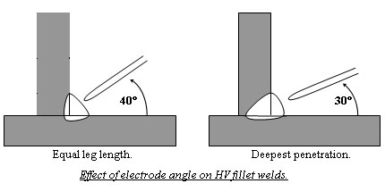
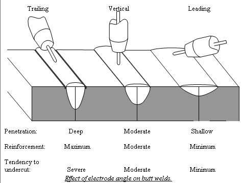
g. Electrode angle.
Since the angle between the electrode and the plate determines the point of application and direction of the arc force it has a profound effect on both penetration and undercut. The first figure shows the effect on horizontal/vertical fillet welds and the second figure compares the effect obtained with a vertical arc with those obtained with leading and trailing arcs. The effect on undercutting can be particularly marked.
h. Flux depth.
The depth of the flux, or flux burden, is often ignored and the powder heaped around the wire until the arc is completely covered. If optimum results are to be obtained the flux depth should be just sufficient to cover the arc, although the point where the electrode enters the flux bed light reflected from the arc should be just visible. Too shallow a flux bed gives flash-through and can cause porosity because of inadequate metallurgical protection of the molten metal. Too deep a flux bed gives a poor bead appearance and can lead to spillage on circumferential welds. On deep preparations in thick plate it is particularly important to avoid excessive flux depth otherwise the weld bead shape and slag removal can be unsatisfactory.
Fluxes.
Fluxes are graded by basicity index and in two types - agglomerated and fused. Particle size is important with larger currents requiring finer fluxes.
Fused fluxes are dark brown or black in colour with a glasslike surface and flakey in shape. They give a good surface profile and reasonable properties. Fused fluxes are general purpose fluxes that require no preheating.
Agglomerated fluxes are light in colour and roughly spherical in shape. They give the best mechanical properties and low hydrogen potential possible requiring the flux to be preheated (baked). Agglomerated fluxes absorb moisture so at the end of work they must be removed and dried.
|