GENERAL DESCRIPTION AND WELDABILITY OF FERROUS METALS
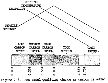
a. General. The low carbon (mild) steels include those with a carbon content of up to 0.30 percent (fig. 7-7). In most low carbon steels, carbon ranges from 0.10 to 0.25 percent, manganese from 0.25 to 0.50 percent, phosphorous 0.40 percent maximum, and sulfur 0.50 percent maximum. Steels in this range are most widely used for industrial fabrication and construction. These low carbon steels do not harden appreciably when welded, and therefore do not require preheating or postheating except in special cases, such as when heavy sections are to be welded. In general, no difficulties are encountered when welding low carbon steels. Properly made low carbon steel welds will equal or exceed the base metal in strength. Low carbon steels are soft, ductile, can be rolled, punched, sheared, and worked when either hot or cold. They can be machined and are readily welded. Cast steel has a rough, dark gray surface except where machined. Rolled steel has fine surface lines running in one direction. Forged steel is usually recognizable by its shape, hammer marks, or fins. The fracture color is bright crystalline gray, and the spark test yields sparks with long, yellow-orange streaks that have a tendency to burst into white, forked sparklers. Steel gives off sparks when melted and solidifies almost instantly. Low carbon steels can be easily welded with any of the arc, gas, and resistance welding processes.
b. Copper coated low carbon rods should be used for welding low carbon steel. The rod sizes for various plate thicknesses are as follows:
Plate thickness
1/16 to 1/8 in. (1.6 to 3.2 mm)
1/8 to 3/8 in. (3.2 to 9.5 mm)
3/8 to 1/2 in. (9.5 to 12.7 mm)
1/2 in. (12.7mm) and heavier |
Rod diameter
1/16 in. (1.6 mm)
1/8 in. (3.2 mm)
3/16 in. (4.8 mm)
1/4 in. (6.4 mm) |
NOTE
Rods from 5/16 to 3/8 in. (7.9 to 9.5 mm) are available for heavy welding. However, heavy welds can be made with the 3/16 or 1/4 in. (4.8 or 6.4 mm) rods by properly controlling the puddle and melting rate of the rod.
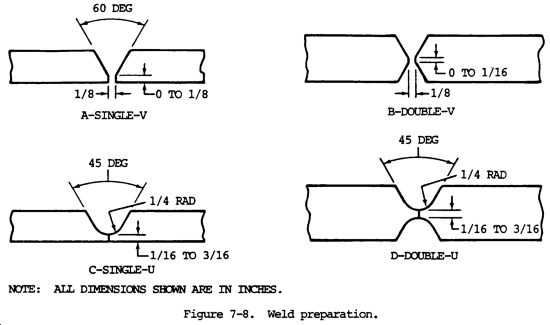
c. The joints may be prepared by flame cutting or machining. The type of preparation (fig. 7-8) is determined by the plate thickness and the welding position.
d. The flame should be adjusted to neutral. Either the forehand or backhand welding method may be used, depending on the thickness of the plates being welded.
e. The molten metal should not be overheated, because this will cause the metal to boil and spark excessively. The resultant grain structure of the weld metal will be large, the strength lowered, and the weld badly scarred.
f. The low carbon steels do not harden in the fusion zone as a result of welding.
g. Metal-Arc Welding.
(1) When metal-arc welding low carbon steels, the bare, thin coated or heavy coated shielded arc types of electrodes may be used. These electrodes are of low carbon type (0.10 to 0.14 percent).
(2) Low carbon sheet or plate materials that have been exposed to low temperatures should be preheated slightly to room temperature before welding.
(3) In welding sheet metal up to 1/8 in. (3.2 mm) in thickness, the plain square butt joint type of edge preparation may be used. When long seams are to be welded in these materials, the edges should be spaced to allow for shrinkage, because the deposited metal tends to pull the plates together. This shrinkage is less severe in arc welding than in gas welding, and spacing of approximately 1/8 in. (3.2 mm) will be sufficient.
(4) The backstep, or skip, welding technique should be used for short seams that are fixed in place. This will prevent warpage or distortion, and will minimize residual stresses.
(5) Heavy plates should be beveled to provide an included angle of up to 60 degrees, depending on the thickness. The parts should be tack welded in place at short intervals along the seam. The first, or root, bead should be made with an electrode small enough in diameter to obtain good penetration and fusion at the base of the joint. A 1/8 or 5/32 in. (3.2 or 4.0 mm) electrode is suitable for this purpose. The first bead should be thoroughly cleaned by chipping and wire brushing before additional layers of weld metal are deposited. Additional passes of the filler metal should be made with a 5/32 or 3/16 in. (4.0 or 4.8 mm) electrode. The passes should be made with a weaving motion for flat, horizontal, or vertical positions. When overhead welding, the best results are obtained by using string beads throughout the weld.
(6) When welding heavy sections that have been beveled from both sides, the weave beads should be deposited alternately on one side and then the other. This will reduce the amount of distortion in the welded structure. Each bead should be cleaned thoroughly to remove all scale, oxides, and slag before additional metal is deposited. The motion of the electrode should be controlled so as to make the bead uniform in thickness and to prevent undercutting and overlap at the edges of the weld. All slag and oxides must be removed from the surface of the completed weld to prevent rusting.
h. Carbon-Arc Welding. Low carbon sheet and plate up to 3/4 in. (19.0 mm) in thickness can be welded using the carbon-arc welding process. The arc is struck against the plate edges, which are prepared in a manner similar to that required for metal-arc welding. A flux should be used on the joint and filler metal should be added as in oxyacetylene welding. A gaseous shield should be provided around the molten base. Filler metal, by means of a flux coated welding rod, should also be provided. Welding must be done without overheating the molten metal. Failure to observe these precautions can cause the weld metal to absorb an excessive amount of carbon from the electrode and oxygen and nitrogen from the air, and cause brittleness in the welded joint.
a. General. Medium carbon steels are non-alloy steels which contain from 0.30 to 0.55 percent carbon. These steels may be heat treated after fabrication and used for general machining and forging of parts which require surface hardness and strength. They are manufactured in bar form and in the cold rolled or the normalized and annealed condition. When heat treated steels are welded, they should be preheated from 300 to 500°F (149 to 260°C), depending on the carbon content (0.25 to 0.45 percent) and the thickness of the steel. The preheating temperature may be checked by applying a stick of 50-50 solder (melting point 450°F (232°C)) to the plate at the joint, and noting when the solder begins to melt. During welding, the weld zone will become hardened if cooled rapidly, and must be stress relieved after welding. Medium carbon steels may be welded with any of the arc, gas, and resistance welding processes.
b. With higher carbon and manganese content, the low-hydrogen type electrodes should be used, particularly in thicker sections. Electrodes of the low-carbon, heavy coated, straight or reverse polarity type, similar to those used for metal-arc welding of low carbon steels, are satisfactory for welding medium carbon steels.
c. Small parts should be annealed to induce softness before welding. The parts should be preheated at the joint and welded with a filler rod that produces heat treatable welds. After welding, the entire piece should be heat treated to restore its original properties.
d. Either a low carbon or high strength rod can be used for welding medium carbon steels. The welding flame should be adjusted to slightly carburizing, and the puddle of metal kept as small as possible to make a sound joint. Welding with a carburizing flame causes the metal to heat quickly, because heat is given off when steel absorbs carbon. This permits welding at higher speeds.
e. Care should be taken to slowly cool the parts after welding to prevent cracking of the weld. The entire welded part should be stress relieved by heating to between 1100 and 1250°F (593 and 677°C) for one hour per inch (25.4 mm) of thickness, and then slowly cooling. Cooling can be accomplished by covering the parts with fire resistant material or sand.
f. Medium carbon steels can be brazed by using a preheat of 200 to 400°F (93 to 204°C), a good bronze rod, and a brazing flux. However, these steels are better welded by the metal-arc process with mild steel shielded arc electrodes.
g. When welding mild steels, keep the following general techniques in mind:
(1) The plates should be prepared for welding in a manner similar to that used for welding low carbon steels. When welding with low carbon steel electrodes, the welding heat should be carefully controlled to avoid overheating the weld metal and excessive penetration into the side walls of the joint. This control is accomplished by directing the electrode more toward the previously deposited filler metal adjacent to the side walls than toward the side walls directly. By using this procedure, the weld metal is caused to wash up against the side of the joint and fuse with it without deep or excessive penetration.
(2) High welding heats will cause large areas of the base metal in the fusion zone adjacent to the welds to become hard and brittle. The area of these hard zones in the base metal can be kept to a minimum by making the weld with a series of small string or weave beads, which will limit the heat input. Each bead or layer of weld metal will refine the grain in the weld immediately beneath it, and will anneal and lessen the hardness produced in the base metal by the previous bead.
(3) When possible, the finished joint should be heat treated after welding. Stress relieving is normally used when joining mild steel, and high carbon alloys should be annealed.
(4) In welding medium carbon steels with stainless steel electrodes, the metal should be deposited in string beads in order to prevent cracking of the weld metal in the fusion zone. When depositing weld metal in the upper layers of welds made on heavy sections, the weaving motion of the electrode should not exceed three electrode diameters.
(5) Each successive bead of weld should be chipped, brushed, and cleaned prior to the laying of another bead.
a. General. High carbon steels include those with a carbon content exceeding 0.55 percent. The unfinished surface of high carbon steels is dark gray and similar to other steels. High carbon steels usually produce a very fine grained fracture, whiter than low carbon steels. Tool steel is harder and more brittle than plate steel or other low carbon material. High carbon steel can be hardened by heating to a good red and quenching in water. Low carbon steel, wrought iron, and steel castings cannot be hardened. Molten high carbon steel is brighter than low carbon steel, and the melting surface has a cellular appearance. It sparks more freely than low carbon (mild) steel, and the sparks are whiter. These steels are used to manufacture tools which are heat treated after fabrication to develop the hard structure necessary to withstand high shear stress and wear. They are manufactured in bar, sheet, and wire forms, and in the annealed or normalized and annealed condition in order to be suitable for machining before heat treatment. The high carbon steels are difficult to weld because of the hardening effect of heat at the welded joint. Because of the high carbon content and the heat treatment usually given to these steels, their basic properties are impaired by arc welding.
b. The welding heat changes the properties of high carbon steel in the vicinity of the weld. To restore the original properties, heat treatment is necessary.
c. High carbon steels should be preheated from 500 to 800°F (260 to 427°C) before welding. The preheating temperature can be checked with a pine stick, which will char at these temperatures.
d. Since high carbon steels melt at lower temperatures than low and medium carbon steels, care should be taken not to overheat the weld or base metal. Overheating is indicated by excessive sparking of the molten metal. Welding should be completed as soon as possible and the amount of sparking should be used as a check on the welding heat. The flame should be adjusted to carburizing. This type of flame tends to produce sound welds.
e. Either a medium or high carbon welding rod should be used to make the weld. After welding, the entire piece should be stress relieved by heating to between 1200 and 1450°F (649 and 788°C) for one hour per inch (25.4 mm) of thickness, and then slowly cooling. If the parts can easily be softened before welding, a high carbon welding rod should be used to make the joint. The entire piece should then be heat treated to restore the original properties of the base metal.
f. In some cases, minor repairs to these steels can be made by brazing. This process does not require temperatures as high as those used for welding, so the properties of the base metal are not seriously affected. Brazing should only be used in special cases, because the strength of the joint is not as high as the original base metal.
g. Either mild or stainless steel electrodes can be used with high carbon steels.
h. Metal-arc welding in high carbon steels requires critical control of the weld heat. The following techniques should be kept in mind:
(1) The welding heat should be adjusted to provide good fusion at the side walls and root of the joint without excessive penetration. Control of the welding heat can be accomplished by depositing the weld metal in small string beads. Excessive puddling of the metal should be avoided, because this can cause carbon to be picked up from the base metal, which in turn will make the weld metal hard and brittle. Fusion between the filler metal and the side walls should be confined to a narrow zone. Use the surface fusion procedure prescribed for medium carbon steels (para 7-11).
(2) The same procedure for edge preparation, cleaning of the welds, and sequence of welding beads as prescribed for low and medium carbon steels also applies to high carbon steels.
(3) Small, high carbon steel parts are sometimes repaired by building up worn surfaces. When this is done, the piece should be annealed or softened by heating to a red heat and cooling slowly. The piece should then be welded or built up with medium carbon or high strength electrodes, and heat treated after welding to restore its original properties.
7-13. TOOL STEELS
a. General. Steels used for making tools, punches, and dies are perhaps the hardest, strongest, and toughest steels used in industry. In general, tool steels are medium to high carbon steels with specific elements included in different amounts to provide special characteristics. A spark test shows a moderately large volume of white sparks having many fine, repeating bursts.
b. Carbon is provided in tool steel to help harden the steel for cutting and wear resistance. Other elements are added to provide greater toughness or strength. In some cases, elements are added to retain the size and shape of the tool during its heat treat hardening operation, or to make the hardening operation safer and to provide red hardness so that the tool retains its hardness and strength when it becomes extremely hot. Iron is the predominant element in the composition of tool steels. Other elements added include chromium, cobalt, manganese, molybdenum, nickel, tungsten, and vanadium. The tool or die steels are designed for special purposes that are dependent upon composition. Certain tool steels are made for producing die blocks; some are made for producing molds, others for hot working, and others for high-speed cutting application.
c. Another way to classify tool steels is according to the type of quench required to harden the steel. The most severe quench after heating is the water quench (water-hardening steels). A less severe quench is the oil quench, obtained by cooling the tool steel in oil baths (oil-hardening steels). The least drastic quench is cooling in air (air-hardening steels).
d. Tool steels and dies can also be classified according to the work that is to be done by the tool. This is based on class numbers.
(1) Class I steels are used to make tools that work by a shearing or cutting actions, such as cutoff dies, shearing dies, blanking dies, and trimming dies.
(2) Class II steels are used to make tools that produce the desired shape of the part by causing the material being worked, either hot or cold, to flow under tension. This includes drawing dies, forming dies, reducing dies, forging dies, plastic molds, and die cast molding dies.
(3) Class III steels are used to make tools that act upon the material being worked by partially or wholly reforming it without changing the actual dimensions. This includes bending dies, folding dies, and twisting dies.
(4) Class IV steels are used to make dies that work under heavy pressure and that produce a flow of metal or other material caressing it into the desired form. This includes crimping dies, embossing dies, heading dies, extrusion dies, and staking dies.
e. Steels in the tool steels group have a carbon content ranging from 0.83 to 1.55 percent. They are rarely welded by arc welding because of the excessive hardness produced in the fusion zone of the base metal. If arc welding must be done, either mild steel or stainless steel electrodes can be used.
f. Uniformly high preheating temperatures (up to 1000°F (583°C)) must be used when welding tool steels.
g. In general, the same precautions should be taken as those required for welding high carbon steels. The welding flare should be adjusted to carburizing to prevent the burning out of carbon in the weld metal. The welding should be done as quickly as possible, taking care not to overheat the molten metal. After welding, the steel should be heat treated to restore its original properties.
h. Drill rods can be used as filler rods because their high carbon content compares closely with that of tool steels.
i. A flux suitable for welding cast iron should be used in small quantities to protect the puddle of high carbon steel and to remove oxides in the weld metal.
j. Welding Technique. When welding tool steels, the following techniques should be kept in mind:
(1) If the parts to be welded are small, they should be annealed or softened before welding. The edges should then be preheated up to 1000°F (538°C), depending on the carbon content and thickness of the plate. Welding should be done with either a mild steel or high strength electrode.
(2) High carbon electrodes should not be used for welding tool steels. The carbon picked up from the base metal by the filler metal will cause the weld to become glass hard, whereas the mild steel weld metal can absorb additional carbon without becoming excessively hard. The welded part should then be heat treated to restore its original properties.
(3) When welding with stainless steel electrodes, the edge of the plate should be preheated to prevent the formation of hard zones in the base metal. The weld metal should be deposited in small string beads to keep the heat input to a minimum. In general, the application procedure is the same as that required for medium and high carbon steels.
k. There are four types of die steels that are weld repairable. These are water-hardening dies, oil-hardening dies, air-hardening dies, and hot work tools. High-speed tools can also be repaired.
7-14. HIGH HARDNESS ALLOY STEELS
a. General. A large number and variety of obtain high strength, high hardness, corrosion alloy steels have been developed to resistance, and other special properties. Most of these steels depend on a special heat treatment process in order to develop the desired characteristic in the finished state. Alloy steels have greater strength and durability than other carbon steels, and a given strength is secured with less material weight.
b. High hardness alloy steels include the following:
(1) Chromium alloy steels. Chromium is used as an alloying element in carbon steels to increase hardenability, corrosion resistance, and shock resistance, and gives high strength with little loss in ductility. Chromium in large amounts shortens the spark stream to one half that of the same steel without chromium, but does not affect the stream's brightness.
(2) Nickel alloy steels. Nickel increases the toughness, strength, and ductility of steels, and lowers the hardening temperature so that an oil quench, rather than a water quench, is used for hardening. The nickel spark has a short, sharply defined dash of brilliant light just before the fork.
(3) High chromium-nickel alloy (stainless) steels. These high alloy steels cover a wide range of compositions. Their stainless, corrosion, and heat resistant properties vary with the alloy content, and are due to the formation of a very thin oxide film which forms on the surface of the metal. Sparks are straw colored near the grinding wheel, and white near the end of the streak. There is a medium volume of streaks which have a moderate number of forked bursts.
(4) Manganese alloy steels. Manganese is used in steel to produce greater toughness, wear resistance, easier hot rolling, and forging. An increase in manganese content decreases the weldability of steel. Steels containing manganese produce a spark similar to a carbon spark. A moderate increase in manganese increases the volume of the spark stream and the intensity of the bursts. A steel containing more than a normal amount of manganese will produce a spark similar to a high carbon steel with a lower manganese content.
(5) Molybdenum alloy steels. Molybdenum increases hardenability, which is the depth of hardening possible through heat treatment. The impact fatigue property of the steel is improved with up to 0.60 percent molybdenum. Above 0.60 percent molybdenum, the impact fatigue proper is impaired. Wear resistance is improved with molybdenum content above about 0.75 percent. Molybdenum is sometimes combined with chromium, tungsten, or vanadium to obtain desired properties. Steels containing this element produce a characteristic spark with a detached arrowhead similar to that of wrought iron, which can be seen even in fairly strong carbon bursts. Molybdenum alloy steels contain either nickel and/or chromium.
(6) Titanium and columbium (niobium) alloy steels. These elements are used as additional alloying agents in low carbon content, corrosion resistant steels. They support resistance to intergranular corrosion after the metal is subjected to high temperatures for a prolonged period of time.
(7) Tungsten alloy steels. Tungsten, as an alloying element in tool steel, tends to produce a fine, dense grain when used in relatively small quantities. When used in larger quantities, from 17 to 20 percent, and in combination with other alloys, tungsten produces a steel that retains its hardness at high temperatures. This element is usually used in combination with chromium or other alloying agents. In a spark test, tungsten will show a dull red color in the spark stream near the wheel. It also shortens the spark stream and decreases the size of or completely eliminates the carbon burst. A tungsten steel containing about 10 percent tungsten causes short, curved, orange spear points at the end of the carrier lines. Still lower tungsten content causes small, white bursts to appear at the end of the spear petit. Carrier lines may be from dull red to orange, depending on the other elements present, providing the tungsten content is not too high.
(8) Vanadium alloy steels. Vanadium is used to help control grain size. It tends to increase hardenability and causes marked secondary hardness, yet resists tempering. It is added to steel during manufacture to remove oxygen. Alloy steels containing vanadium produce sparks with detached arrowheads at the end of the carrier line similar to those produced by molybdenum steels.
(9) Silicon alloy steels. Silicon is added to steel to obtain greater hardenability and corrosion resistance. It is often used with manganese to obtain a strong, tough steel.
(10) High speed tool steels. These steels are usually special alloy compositions designed for cutting tools. The carbon content ranges from 0.70 to 0.80 percent. They are difficult to weld, except by the furnace induction method. A spark test will show a few long, forked spades which are red near the wheel, and straw colored near the end of the spark stream.
c. Many of these steels can be welded with a heavy coated electrode of the shielded arc type, whose composition is similar to that of the base metal. Low carbon electrodes can also be used with some steels. Stainless steel electrodes are effective where preheating is not feasible or desirable. Heat treated steels should be preheated, if possible, in order to minimize the formation of hard zones, or layers, in the base metal adjacent to the weld. The molten metal should not be overheated, and the welding heat should be controlled by depositing the metal in narrow string beads. In many cases, the procedures for welding medium carbon steels (para 7-11) and high carbon steels (para 7-12) can be used in the welding of alloy steels.
7-15. HIGH YIELD STRENGTH, LOW ALLOY STRUCTURAL STEELS
a. General. High yield strength, low alloy structural steels (constructional alloy steels) are special steels that are tempered to obtain extreme toughness and durability. The special alloys and general makeup of these steels require special treatment to obtain satisfactory weldments. These steels are special, low-carbon steels containing specific, small amounts of alloying elements. They are quenched and tempered to obtain a yield strength of 90,000 to 100,000 psi (620,550 to 689,500 kPa) and a tensile strength of 100,000 to 140,000 psi (689,500 to 965,300 kPa), depending upon size and shape. Structural members fabricated from these high strength steels may have smaller cross-sectional areas than common structural steels and still have equal strength. These steels are also more corrosion and abrasion resistant than other steels. In a spark test, these alloys produce a spark very similar to low carbon steels.
b. Welding Technique. Reliable welding of high yield strength, low alloy structural steels can be performed by using the following guidelines:
CAUTION
To prevent underbead cracking, only low hydrogen electrodes should be used when welding high yield strength, low alloy structural steels.
(1) Correct electrodes. Hydrogen is the number one enemy of sound welds in alloy steels; therefore, use only low hydrogen (MIL-E-18038 or MIL-E-22200/1) electrodes to prevent underbead cracking. Underbead cracking is caused by hydrogen picked up in the electrode coating, released into the arc, and absorbed by the molten metal.
(2) Moisture control of electrodes. If the electrodes are in an airtight container, place them, immediately upon opening the container, in a ventilated holding oven set at 250 to 300°F (121 to 149°C). In the event that the electrodes are not in an airtight container, put them in a ventilated baking oven and bake for 1-1/4 hours at 800°F (427°C). Baked electrodes should, while still warm, be placed in the holding oven until used. Electrodes must be kept dry to eliminate absorption of hydrogen. Testing for moisture should be in accordance with MIL-E-22200.
NOTE
Moisture stabilizer NSN 3439-00-400-0090 is an ideal holding oven for field use (MIL-M-45558).
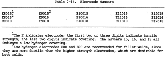
c. Low Hydrogen Electrode Selection. Electrodes are identified by classification numbers which are always marked on the electrode containers. For low hydrogen coatings, the last two nunbers of the classification should be 15, 16, or 18. Electrodes of 5/32 and 1/8 in. (4.0 and 3.2 mm) in diameter are the most commonly used, since they are more adaptable to all types of welding of this type steel. Table 7-14 lists electrodes used to weld high yield strength, low alloy structural steels. Table 7-15 is a list of electrodes currently established in the Army supply system.

d. Selecting Wire-Flux and Wire-Gas Combinations. Wire electrodes for submerged arc and gas-shielded arc welding are not classified according to strength. Welding wire and wire-flux combinations used for steels to be stress relieved should contain no more than 0.05 recent vanadium. Weld metal with more than 0.05 percent vanadium may brittle if stress relieved. When using either the submerged arc or gas metal-arc welding processes to weld high yield strength, low alloy structural steels to lower strength steels the wire-flux and wire-gas combination should be the same as that recommended for the lower strength steels.
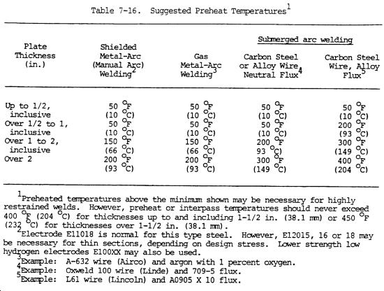
e. Preheating. For welding plates under 1.0 in. (25.4 mm) thick, above 50°F (10°C) is not required except to remove surface moisture metal. Table 7-16 contains suggested preheating temperatures.
f. Welding Heat.
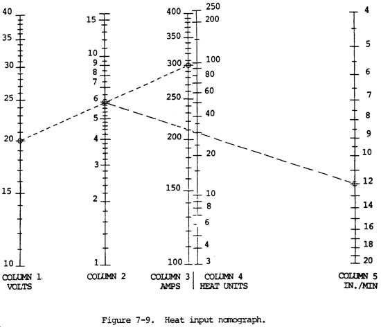
(1) General. It is important to avoid excessive heat concentration in order to allow the weld area to cool quickly. Either the heat input nomograph or the heat input calculator can be used to determine the heat input into the weld.
(2) Heat input nomograph. To use the heat input nomograph (fig. 7-9), find the volts value in column 1 and draw a line to the amps value in column 3. From the point where this line intersects colunm 2, draw another line to the in./min value in column 5. Read the heat units at the point where this second line intersects column 4. The heat units represent thousands of joules per inch. For example, at 20 volts and 300 amps, the line intersects column 2 at the value 6. At 12 in./min, the heat input is determined as 30 heat units, or 30,000 joules/in.
(3) Heat input calculator. The heat input calculator can be made by copying the pattern printed on the inside of the back cover of this manual onto plastic, light cardboard, or other suitable material and cutting out the pieces. If no suitable material is available, the calculator may be assembled by cutting the pattern out of the back cover. After the two pieces are cut out, a hole is punched in the center of each. They are then assembled using a paper fastener, or some similar device, which will allow the pieces to rotate. To determine welding heat input using the calculator, rotate until the value on the volts scale is aligned directly opposite the value on the speed (in./min) scale. The value on the amps scale will then be aligned directly opposite the calculated value for heat units. As with the nomograph, heat units represent thousands of joules per inch.
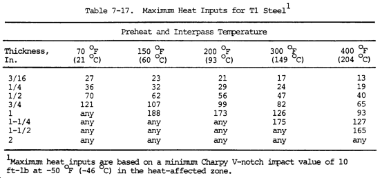
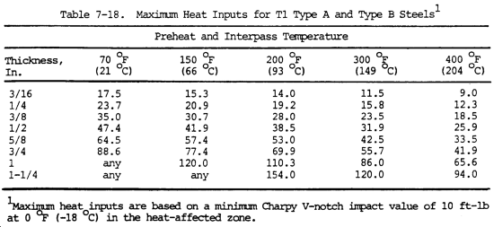
(4) Maximum heat input. Check the heat input value obtained from the nomograph or calculator against the suggested maximums in tables 7-17 and 7-18. If the calculated value is too high, adjust the amperes, travel speed, or preheat temperature until the calculated heat input is within the proper range. (The tables are applicable only to single-arc, shielded metal-arc, submerged arc, gas tungsten-arc, flux-cored arc, and gas metal-arc processes. They are not applicable to multiple-arc or electroslag welding, or other high heat input vertical-welding processes, since welds made by these in the "T-1" steels should be heat treated by quenching and tempering.) For welding conditions exceeding the range of the nomograph or calculator, the heat input can be calculated using the following formula:

g. Welding Process. Reliable welding of high yield strength, low alloy structural steel can be per formal by choosing an electrode with low hydrogen content or selecting the proper wire-flux or wire gas combination when using the submerged arc or gas metal arc processes. Use a straight stringer bead whenever possible. Avoid using the weave pattern; however, if needed, it must be restricted to a partial weave pattern. Best results are obtained by a slight circular motion of the electrode with the weave area never exceeding two elect-rode diameters. Never use a full weave pattern. The partial weave pattern should not exceed twice the diameter of the electrode. Skip weld as practical. Peening of the weld is sometimes recommended to relieve stresses while cooling larger pieces. Fillet welds should be smooth and correctly contoured. Avoid toe cracks and undercutting. Electrodes used for fillet welds should be of lower strength than those used for butt welding. Air-hammer peening of fillet welds can help to prevent cracks, especially if the welds are to be stress relieved. A soft steel wire pedestal can help to absorb shrinkage forces. Butter welding in the toe area before actual fillet welding strengths the area where a toe crack may start. A bead is laid in the toe area, then ground off prior to the actual fillet welding. This butter weld bead must be located so that the toe of the fillet will be laid directly over it during actual fillet welding. Because of the additional material involved in fillet welding, the cooling rate is increased and heat inputs may be extended about 25 percent.
7-16. CAST IRON
a. General. A cast iron is an alloy of iron, carbon, and silicon, in which the amount of carbon is usually more than 1.7 percent and less than 4.5 percent.
(1) The most widely used type of cast iron is known as gray iron. Gray iron has a variety of compositions, but is usually such that it is primarily perlite with many graphite flakes dispersed throughout.
(2) There are also alloy cast irons which contain small amounts of chromium, nickel, molybdenum, copper, or other elements added to provide specific properties.
(3) Another alloy iron is austenitic cast iron, which is modified by additions of nickel and other elements to reduce the transformation temperature so that the structure is austenitic at room or normal temperatures. Austenitic cast irons have a high degree of corrosion resistance.
(4) In white cast iron, almost all the carbon is in the combined form. This provides a cast iron with higher hardness, which is used for abrasion resistance.
(5) Malleable cast iron is made by giving white cast iron a special annealing heat treatment to change the structure of the carbon in the iron. The structure is changed to perlitic or ferritic, which increases its ductility.
(6) Nodular iron and ductile cast iron are made by the addition of magnesium or aluminum which will either tie up the carbon in a combined state or will give the free carbon a spherical or nodular shape, rather than the normal flake shape in gray cast iron. This structure provides a greater degree of ductility or malleability of the casting.
(7) Cast irons are widely used in agricultural equipment; on machine tools as bases, brackets, and covers; for pipe fittings and cast iron pipe; and for automobile engine blocks, heads, manifolds, and water preps. Cast iron is rarely used in structural work except for compression members. It is widely used in construction machinery for counterweights and in other applications for which weight is required.
b. Gray cast iron has low ductility and therefore will not expand or stretch to any considerable extent before breaking or cracking. Because of this characteristic, preheating is necessary when cast iron is welded by the oxyacetylene welding process. It can, however, be welded with the metal-arc process without preheating if the welding heat is carefully controlled. This can be accomplished by welding only short lengths of the joint at a time and allowing these sections to cool. By this procedure, the heat of welding is confined to a small area, and the danger of cracking the casting is eliminated. Large castings with complicated sections, such as motor blocks, can be welded without dismantling or preheating. Special electrodes designed for this purpose are usually desirable. Ductile cast irons, such as malleable iron, ductile iron, and nodular iron, can be successfully welded. For best results, these types of cast irons should be welded in the annealed condition.
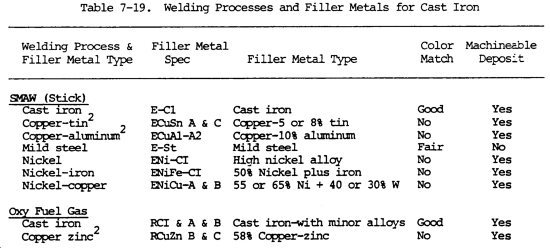
c. Welding is used to salvage new iron castings, to repair castings that have failed in service, and to join castings to each other or to steel parts in manufacturing operations. Table 7-19 shows the welding processes that can be used for welding cast, malleable, and nodular irons. The selection of the welding process and the welding filler metals depends on the type of weld properties desired and the service life that is expected. For example, when using the shielded metal arc welding process, different types of filler metal can be used. The filler metal will have an effect on the color match of the weld compared to the base material. The color match can be a determining factor, specifically in the salvage or repair of castings, where a difference of color would not be acceptable.
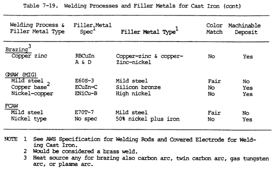
d. No matter which of the welding processes is selected, certain preparatory steps should be made. It is important to determine the exact type of cast iron to be welded, whether it is gray cast iron or a malleable or ductile type. If exact information is not known, it is best to assume that it is gray cast iron with little or no ductility. In general, it is not recommended to weld repair gray iron castings that are subject to heating and cooling in normal service, especially when heating and cooling vary over a range of temperatures exceeding 400°F (204°C). Unless cast iron is used as the filler material, the weld metal and base metal may have different coefficients of expansion and contraction. This will contribute to internal stresses which cannot be withstood by gray cast iron. Repair of these types of castings can be made, but the reliability and service life on such repairs cannot be predicted with accuracy.
e. Preparation for Welding.
(1) In preparing the casting for welding, it is necessary to remove all surface materials to completely clean the casting in the area of the weld. This means removing paint, grease, oil, and other foreign material from the weld zone. It is desirable to heat the weld area for a short time to remove entrapped gas from the weld zone of the base metal. The skin or high silicon surface should also be removed adjacent to the weld area on both the face and root side. The edges of a joint should be chipped out or ground to form a 60° angle or bevel. Where grooves are involved, a V groove from a 60-90° included angle should be used. The V should extend approximately 1/8 in. (3.2 mm) from the bottom of the crack. A small hole should be drilled at each end of the crack to keep it from spreading. Complete penetration welds should always be used, since a crack or defect not completely removed may quickly reappear under service conditions.
(2) Preheating is desirable for welding cast irons with any of the welding processes. It can be reduced when using extremely ductile filler metal. Preheating will reduce the thermal gradient between the weld and the remainder of the cast iron. Preheat temperatures should be related to the welding process, the filler metal type, the mass, and the complexity of the casting. Preheating can be done by any of the normal methods. Torch heating is normally used for relatively small castings weighing 30.0 lb (13.6 kg) or less. Larger parts may be furnace preheated, and in some cases, temporary furnaces are built around the part rather than taking the part to a furnace. In this way, the parts can be maintained at a high interpass temperature in the temporary furnace during welding. Preheating should be general, since it helps to improve the ductility of the material and will spread shrinkage stresses over a large area to avoid critical stresses at any one point. Preheating tends to help soften the area adjacent to the weld; it assists in degassing the casting, and this in turn reduces the possibility of porosity of the deposited weld metal; and it increases welding speed.
(3) Slow cooling or post heating improves the machinability of the heat-affected zone in the cast iron adjacent to the weld. The post cooling should be as slow as possible. This can be done by covering the casting with insulating materials to keep the air or breezes from it.
f. Welding Technique.
(1) Electrodes.
(a) Cast iron can be welded with a coated steel electrode, but this method should be used as an emergency measure only. When using a steel electrode, the contraction of the steel weld metal, the carbon picked up from the cast iron by the weld metal, and the hardness of the weld metal caused by rapid cooling must be considered. Steel shrinks more than cast iron when ceded from a molten to a solid state. When a steel electrode is used, this uneven shrinkage will cause strains at the joint after welding. When a large quantity of filler metal is applied to the joint, the cast iron may crack just back of the line of fusion unless preventive steps are taken. To overcome these difficulties, the prepared joint should be welded by depositing the weld metal in short string beads, 0.75 to 1.0 in. long (19.0 to 25.4 mm). These are made intermittently and, in some cases, by the backstep and skip procedure. To avoid hard spots, the arc should be struck in the V, and not on the surface of the base metal. Each short length of weld metal applied to the joint should be lightly peened while hot with a small ball peen hammer, and allowed to cool before additional weld metal is applied. The peening action forges the metal and relieves the cooling strains.
(b) The electrodes used should be 1/8 in. (3.2 mm) in diameter to prevent excessive welding heat. Welding should be done with reverse polarity. Weaving of the electrode should be held to a minimum. Each weld metal deposit should be thoroughly cleaned before additional metal is added.
(c) Cast iron electrodes must be used where subsequent machining of the welded joint is required. Stainless steel electrodes are used when machining of the weld is not required. The procedure for making welds with these electrodes is the same as that outlined for welding with mild steel electrodes. Stainless steel electrodes provide excellent fusion between the filler and base metals. Great care must be taken to avoid cracking in the weld, contracts approximately 50 percent more than because stainless steel expands and mild steel in equal changes of temperature.
(2) Arc Welding.
(a) The shielded metal arc welding process can be utilized for welding cast iron. There are four types of filler metals that may be used: cast iron covered electrodes; covered copper base alloy electrodes; covered nickel base alloy electrodes; and mild steel covered electrodes. There are reasons for using each of the different specific types of electrodes, which include the machinability of the deposit, the color match of the deposit, the strength of the deposit, and the ductility of the final weld.
(b) When arc welding with the cast iron electrodes (ECI), preheat to between 250 and 800°F (121 and 425°C), depending on the size and complexity of the casting and the need to machine the deposit and adjacent areas. The higher degree of heating, the easier it will be to machine the weld deposit. In general, it is best to use small-size electrodes and a relatively 1ow current setting. A medium arc length should be used, and, if at all possible, welding should be done in the flat position. Wandering or skip welding procedure should be used, and peening will help reduce stresses and will minimize distortion. Slow cooling after welding is recommended. These electrodes provide an excellent color match cm gray iron. The strength of the weld will equal the strength of the base metal. There are two types of copper-base electrodes: the copper tin alloy and the copper aluminum types. The copper zinc alloys cannot be used for arc welding electrodes because of the low boiling temperature of zinc. Zinc will volatilize in the arc and will cause weld metal porosity.
(c) When the copper base electrodes are used, a preheat of 250 to 400°F (121 to 204°C) is recommended. Small electrodes and low current should be used. The arc should be directed against the deposited metal or puddle to avoid penetration and mixing the base metal with the weld metal. Slow cooling is recommended after welding. The copper-base electrodes do not provide a good color match.
(d) There are three types of nickel electrodes used for welding cast iron. These electrodes can be used without preheat; however, heating to 100°F (38°C) is recommended. These electrodes can be used in all positions; however, the flat position is recommended. The welding slag should be removed between passes. The nickel and nickel iron deposits are extremely ductile and will not become brittle with the carbon pickup. The hardness of the heat-affected zone can be minimized by reducing penetration into the cast iron base metal. The technique mentioned above, playing the arc on the puddle rather than on the base metal, will help minimize dilution. Slow cooling and, if necessary, postheating will improve machinability of the heat-affected zone. The nickel-base electrodes do not provide a close color match.
(e) Copper nickel type electrodes cane in two grades. Either of these electrodes can be used in the same manner as the nickel or nickel iron electrode with about the same technique and results. The deposits of these electrodes do not provide a color match.
(f) Mild steel electrodes are not recommended for welding cast iron if the deposit is to be machined. The mild steel deposit will pick up sufficient carbon to make a high-carbon deposit, which is impossible to machine. Additionally, the mild steel deposit will have a reduced level of ductility as a result of increased carbon content. This type of electrode should be used only for small repairs and should not be used when machining is required. Minimum preheat is possible for small repair jobs. Small electrodes at low current are recommended to minimize dilution and to avoid the concentration of shrinkage stresses. Short welds using a wandering sequence should be used, and the weld should be peened as quickly as possible after welding. The mild steel electrode deposit provides a fair color match.
(3) Carbon-arc welding of cast iron. Iron castings may be welded with a carbon arc, a cast iron rod, and a cast iron welding flux. The joint should be preheated by moving the carbon electrodes along the surface. This prevents too-rapid cooling after welding. The molten puddle of metal can be worked with the carbon electrode so as to move any slag or oxides that are formed to the surface. Welds made with the carbon arc cool more slowly and are not as hard as those made with the metal arc and a cast iron electrode. The welds are machinable.
(4) Oxyfuel gas welding. The oxyfuel gas process is often used for welding cast iron. Most of the fuel gases can be used. The flame should be neutral to slightly reducing. Flux should be used. Two types of filler metals are available: the cast iron rods and the copper zinc rods. Welds made with the proper cast iron electrode will be as strong as the base metal. Good color match is provided by all of these welding reds. The optimum welding procedure should be used with regard to joint preparation, preheat, and post heat. The copper zinc rods produce braze welds. There are two classifications: a manganese bronze and a low-fuming bronze. The deposited bronze has relatively high ductility but will not provide a color match.
(5) Brazing and braze welding.
(a) Brazing is used for joining cast iron to cast iron and steels. In these cases, the joint design must be selected for brazing so that capillary attraction causes the filler metal to flow between closely fitting parts. The torch method is normally used. In addition, the carbon arc, the twin carbon arc, the gas tungsten arc, and the plasma arc can all be used as sources of heat. Two brazing filler metal alloys are normally used; both are copper zinc alloys. Braze welding can also be used to join cast iron. In braze welding, the filler metal is not drawn into the joint by capillary attraction. This is sometimes called bronze welding. The filler material having a liquidous above 850°F (454°C) should be used. Braze welding will not provide a color match.
(b) Braze welding can also be accomplished by the shielded metal arc and the gas metal arc welding processes. High temperature preheating is not usually required for braze welding unless the part is extremely heavy or complex in geometry. The bronze weld metal deposit has extremely high ductility, which compensates for the lack of ductility of the cast iron. The heat of the arc is sufficient to bring the surface of the cast iron up to a temperature at which the copper base filler metal alloy will make a bond to the cast iron. Since there is little or no intermixing of the materials, the zone adjacent to the weld in the base metal is not appreciably hardened. The weld and adjacent area are machinable after the weld is completed. In general, a 200°F (93°C) preheat is sufficient for most application. The cooling rate is not extremely critical and a stress relief heat treatment is not usually required. This type of welding is commonly used for repair welding of automotive parts, agricultural implement parts, and even automotive engine blocks and heads. It can only be used when the absence of color match is not objectionable.
(6) Gas metal arc welding. The gas metal arc welding process can be used for making welds between malleable iron and carbon steels. Several types of electrode wires can be used, including:
(a) Mild steel using 75% argon + 25% CO2 for shielding.
(b) Nickel copper using 100% argon for shielding.
(c) Silicon bronze using 50% argon + 50% helium for shielding.
In all cases, small diameter electrode wire should be used at low current. With the mild steel electrode wire, the Argon-CO2 shielding gas mixture issued to minimize penetration. In the case of the nickel base filler metal and the Copper base filler metal, the deposited filler metal is extremely ductile. The mild steel provides a fair color match. A higher preheat is usually required to reduce residual stresses and cracking tendencies.
(7) Flux-cored arc welding. This process has recently been used for welding cast irons. The more successful application has been using a nickel base flux-cored wire. This electrode wire is normally operated with CO2 shielding gas, but when lower mechanical properties are not objectionable, it can be operated without external shielding gas. The minimum preheat temperatures can be used. The technique should minimize penetration into the cast iron base metal. Postheating is normally not required. A color match is not obtained.
(8) Studding. Cracks in large castings are sometimes repaired by studding (fig. 7-10). In this process, the fracture is removed by grinding a V groove. Holes are drilled and tapped at an angle on each side of the groove, and studs are screwed into these holes for a distance equal to the diameter of the studs, with the upper ends projecting approximately 1/4 in. (6.4 mm) above the cast iron surface. The studs should be seal welded in place by one or two beads around each stud, and then tied together by weld metal beads. Welds should be made in short lengths, and each length peened while hot to prevent high stresses or cracking upon cooling. Each bead should be allowed to cool and be thoroughly cleaned before additional metal is deposited. If the studding method cannot be applied, the edges of the joint should be chipped out or machined with a round-nosed tool to form a U groove into which the weld metal should be deposited.

(9) Other welding processes can be used for cast iron. Thermit welding has been used for repairing certain types of cast iron machine tool parts. Soldering can be used for joining cast iron, and is sometimes used for repairing small defects in small castings. Flash welding can also be used for welding cast iron.
Authorization Letter
|


