We manufacture SAW / ESW cladding heads and supply fully automated systems for all applications .
Strip claddiing is a widely used process for overlaying on material like SS on carbon steel , Low alloy steel etc and also for hardfacing various components like rolls , valves wear plates.
| |
|
 |
 |
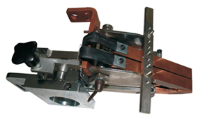
| Strip Cladding Head |
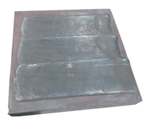
strip cladding sample |
Features:
- Increased deposition rate of 60 – 80%.
- Only half of dilution from base material due to less penetration.
- Lower arc voltage.
- High amperage and current density.
- Increased welding speed resulting in higher area coverage.
- Lower flux consumption.
- The solidification rate of ESW weld metal is lower, aids de-gassing and increases resistance to porosity.
- Oxides can rise easier out of the molten pool to the surface; resulting in a metallurgical cleaner weld metal which is less sensitive to hot cracking and corrosion.
- Due to the properties of ESW often only one layer is needed to fulfill the cladding requirements and further the consumption of consumables is significantly reduced
- ESW can be advantageously used for the productive cladding of a second layer, when the two layer technology is demanded. The first layer, usually a buffer layer, can be deposited with either SAW
or ESW.
Specifications:
- Robustly constructed in order to deliver reliability and consistency in high-production cladding applications.
- Strip width 90, 120, 150 mm
- Water Cooled
- Multiple contact fingers with adjustable tension screws ensure good electrical contact across the width of the strip.
- Air-cooled coil housing prevents electromagnets from excessive heating, reducing droops in magnetic strength.
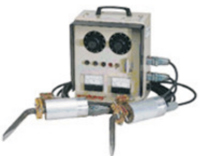
Magnetic Stirrer:
 |
- The slag pool is electro conductive; therefore, the slag pool is subjected to EM forces that tend to make it flow from the sides towards the centre of the molten pool resulting in narrower beads and unfavorable wetting angles. Slag removal becomes difficult and there will be more chances of LF in bead overlap area.
- To compensate for this, magnetic devices are used. This magnetic field is creating by means of two solenoids. The location of solenoids is very important. The tips should be placed beside the strip electrode at a dist. off approx. 15mm from the strip edge and about 15 mm above the base material surface.
- The shape of the solidification ripples should be used to control the intensity of the magnetic field. The criterion for correct intensity of the magnetic field is when the solidification lines become symmetrical.
It is obvious that the intensity on each solenoid has to be adapted to the working conditions on a particular w/p, taking into account any magnetic blow effect that cannot be calculated previously.
- In order to obtain an optimal bead shape during strip cladding, magnetic steering device is used to control the magnetic influences of the high currents flowing through the strip. Recommended for 60mm and above strip.
|
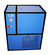
Water Chiller:
| |
Features |
Specifications |
 |
- Maximizes torch productivity.
- Easily mounted on trolley.
- On – off front panel switch
- Visible temperature indicator
- Available for
- Plasma cutting machine,
- Plasma welding machine,
- PTA welding machine,
- MIG welding machine
|
- Capacity – 3 Ton
- Flow Rate - 5 lpm
- Outlet Temperature - 10 – 25 °C Adjustable)
- Input – 380-415 VAC / 3-Ø / 50-60 Hz
- Power - 0.5 Hp
- Tank – 200 Liters
|
Automation:
Column and Boom (Manipulator): Available in various sizes from 500 to 3000mm for both, column as well as boom.
.
Tank Rotator (Turning Rolls): Heavy duty structure with weight capacity from 2 Ton and above with Lead Screw
/ Bolt / Self Aligning type.
.
Controller: With all necessary parameters to control current, voltage, column & boom, rotator rotation/speed, etc for easy and automatic operation.
Options Available:
.
Power Source: 2000A, Make – Lincoln Electric.
.
Strip Feed Unit: High powered, geared motors are required to unwind the strip from the reel and advance the strip electrode in welding process. This is true particularly when using wide strip electrodes. Grooved feed rollers matching the width of the electrodes will be required.
.
Flux Feed Unit: The granular flux material is normally fed out of the flux hopper, and only in front of the strip electrode. In this way the uncovered slag pool is formed behind the electrode.
What is ESW / SAW Cladding ?
SAW strip cladding
The well-known SAW method has been widely used with strip electrodes since the mid-1950s. A strip electrode, normally measuring 50 x 0.5 mm or 90 x 0.5 mm, is used as the (usually positive) electrode and .an electric arc is formed between the strip and the workpiece. Flux is used to form a molten slag to protect the weld pool from the atmosphere and helps to form a smooth weld bead surface.
ESW strip cladding
Electroslag strip cladding is a development of submerged arc strip cladding which has quickly established itself as a reliable high deposition rate process. ESW strip cladding relates to the resistance welding processes and is based on the ohmic resistance heating of a molten electrically conductive slag.
There is no arc between the strip electrode and the parent material. The heat generated by the molten slag melts the surface of the base material, and the edge of the strip electrode is submerged in the slag and flux.
The penetration achieved with ESW is less than that with for SAW because the molten slag pool is used to melt the strip and some of the parent material. The temperature of .the slag pool is about 2300°C, making it to water-cool the contact jaws.
ESW uses higher welding currents than SAW strip cladding so the welding heads used are more heavy duty. The following shows the features of ESW compared with the strip cladding process.
|


